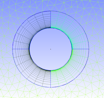
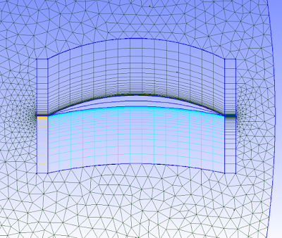
If you are not familiar with these mesh types, unstructured is the one that can be quickly generated around a complex body with the click of a button. The cells turn out triangular in 2D (usually, and can be 4-sided or more) and usually pyramidal in 3D. Structured meshes are made by specifying point locations on an outer rectangular block. Structured mesh cells turn out to be square / rectangular in 2D and rectangular prismatic in 3D. Structured meshes usually take more time than unstructured.
So why use structured? One important flow phenomenon that cannot be efficiently captured by unstructured meshes is boundary layer separation. For drag simulations, predicting boundary layer separation is key. With structured meshes the cells can have a high aspect ratio to have small spacing normal to the wall to resolve the large velocity gradient, and larger spacing parallel to the wall, in which pressure/velocity gradient is not as huge. Unstructured meshes maintain roughly an equilateral shape, and stretching out unstructured mesh cells results in bad mesh quality in terms of skew. So to get boundary-layer resolution with unstructured would take many more cells than with structured cells; structured cells basically allow you to be more efficient with the cells you use.
So many CFD'ers use both unstructured and structured meshes; unstructured as the default, and structured in special areas of interest. Below are a few pictures of part of a hybrid mesh I created in Gmsh (free) for a 2D simulation in OpenFOAM (also free), and it worked perfectly in parallel simulation.


There are tutorial files on the Gmsh website that show you how to do this easily. Look at tutorial file t6.geo. Good luck!

Hello,
ReplyDeleteI'm a gmsh beginner, and I'll have to build an hybrid mesh with a boundary layer.
I'd really be interested in getting your .geo file then, that could help me to begin.
Is there any chance that you upload it somewhere?
Thanks.
Well my script is quite messy, and I doubt it will be helpful especially since you are a beginner. The tutorial files that I mentioned (t6.geo) that are available on the gmsh website is very helpful. Thats all I needed. I do have some airfoil cases that sometime soon I will upload, once I clean them up.
ReplyDeleteDear Lordvon,
ReplyDeleteThanks for the blog post. It is quite helpful.
I have been trying to obtain a O grid around a cyclindrical configuration quite similar to yours.
I took help of t6.geo tutorial of Gmsh documentation. I have been unsuccessful so far.
Attaching my .geo file below. Can you point out what change I must do to get the O gird as yours (A completely O gird is my requirement without any triangle elements!)
// Gmsh project created on Tue Nov 4 19:03:02 2014
Point(1) = {0, 0, 0, 1.0};
Point(2) = {1, 0, 0, 1.0};
Point(3) = {1, 1, 0, 1.0};
Point(4) = {0, 1, 0, 1.0};
Point(5) = {0.25, 0.5, 0, 1.0};
Point(6) = {0.75, 0.5, 0, 1.0};
Point(7) = {0.5, 0.5, 0, 1.0};
Point(8) = {0.5, 0.25, 0, 1.0};
Point(9) = {0.5, 0.75, 0, 1.0};
Line(1) = {1, 2};
Line(2) = {2, 3};
Line(3) = {3, 4};
Line(4) = {4, 1};
Circle(5) = {9, 7, 5};
Circle(6) = {5, 7, 8};
Circle(7) = {8, 7, 6};
Circle(8) = {6, 7, 9};
Line Loop(9) = {3, 4, 1, 2};
Line Loop(10) = {5, 6, 7, 8};
Plane Surface(11) = {9, 10};
Transfinite Line {5, 8, 7, 6} = 5 Using Progression 0.5;
Transfinite Line {3, 2, 1, 4} = 10 Using Progression 0.1;
Transfinite Surface {11};
Recombine Surface {11};
#####################
Thanks in advance :)
Hi Sangeeth, you need 4-sided shapes to make transfinite meshes with 4-sided cells. Align your circle and square points such that you can make 4, 4-sided shapes, and then do the transfinite process on each of them to get 4 transfinite meshes.
DeleteHello Robert,
ReplyDeleteThis post helped me a lot since I never heard about gmsh before. I went through the tutorials and tried to implement a structured mesh within an unstructured one just like you have. My mesh is OK except for a strange criss crossing in the structured part. I'm not sure what is causing this. Can you tell me where I'm going wrong?
Point(1) = {-10, 10, 0, 1.0};
Point(2) = {10, 10, 0, 1.0};
Point(3) = {-10, -10, 0, 1.0};
Point(4) = {10, -10, 0, 1.0};
//Point(6) = {-1, 0.01, 0, 0.1};
//Point(7) = {1, 0.01, 0, 0.1};
//Point(8) = {-1, -0.01, 0, 0.1};
//Point(9) = {1, -0.01, 0, 0.1};
Point(10) = {-2, 1, 0, 0.1};
Point(11) = {2, 1, 0, 0.1};
Point(12) = {-2, -1, 0, 0.1};
Point(13) = {2, -1, 0, 0.1};
Line(1) = {1, 2};
Line(2) = {2, 4};
Line(3) = {4, 3};
Line(4) = {3, 1};
Line(5) = {10, 11};
Line(6) = {11, 13};
Line(7) = {13, 12};
Line(8) = {12, 10};
//Line(9) = {6, 7};
//Line(10) = {7, 9};
//Line(11) = {9, 8};
//Line(12) = {8, 6};
Line Loop(1) = {1,2,3,4}; //,5,6,7,8};
//Line Loop(2) = {9,10,11,12};
Line Loop(3) = {5,6,7,8};
Plane Surface(1) = {1,3};
Plane Surface(2) = {3};
Transfinite Line {5,7} = 10;
Transfinite Line {6,8} = 10;
Transfinite Surface{2} = {10,13,12,11};
//Recombine Surface{1};
//Plane Surface(2) = {1,2};
//Extrude {0, 0, 1}
// {
// Surface{1};
// Layers{1};
// Recombine;
// }
I commented out the Recombine Surface line and that was the problem. This is what happens when I use a tool without actually understanding the underlying principles. Once again thanks for sharing your work with everyone.
DeleteHi Robert,
ReplyDeleteI generated a hybrid mesh and I'm stuck with a problem. I'm not sure how to handle the internal faces generated by the different mesh regions(structured and unstructured). OpenFOAM declares them as default faces as follows
defaultFaces
{
type patch;
nFaces 284;
startFace 562756;
}
How did you handle this issue? Here is the github link https://github.com/pruthvi1991/gmsh/tree/master/pilot
Here are pictures to help you see what I did https://drive.google.com/open?id=0B0O_EM6xOrebfm5FZE1TYUhqZXNUVlF2d1RfUUdxWU5KenJlbmV4dUN3dXUySnUyTG42WEk&authuser=0
Thanks,
Pruthvi.
Hi Pruthvi,
DeleteI took a look at your mesh and it seems the problem is there are non-conformal regions. If an internal face is recognized by openfoam and put into defaultfaces, then something is wrong, unless you intentionally made non-conformal regions and intend to use AMI or something.
If you look at your mesh at the extrusions of surfaces 5 and 9, you can see that there is some weirdness going on. These surfaces are not extruded as you intend. Specifically, it seems the base surface has a different meshing than the extruded final surface somehow.
That's all I can do right now, but hopefully that is a helpful lead. Let me know if you find the solution!
-Robert
If I were you I would work on getting the extrusions of surfaces 5 and 9 right, and turn off the other extrusions.
DeleteNice analysis Robert! You were right, there were non-conformal regions. I was able to fix the problem by changing the number of points on the transfinite line. Even now the error occurs if I change a progression from 1.02 to 1.03. I guess my meshing technique is not very smart since it creates a sudden jump in mesh size at surfaces 5 and 9. Thanks again!
DeleteAwesome! Glad I could help. Unfortunately Gmsh acts buggy from time to time (though it is possible I have actually done something wrong). Just curious, what are you doing your simulations for?
DeleteI simulate flapping airfoils which have applications in energy harvesting and micro aerial vehicles. We developed an in house code based on the discreet vortex method. We are in the process of validating and improving it.
DeleteHi Robert,
ReplyDeleteYour hybrid mesh looks amazing. I am right now working on creating this kind of hybrid mesh for an airfoil with sharp trailing edge (with GMSH). I used the boundarylayer function, but there are always bad quality meshes near the trailing edge.. there is a fan-shape like mesh that spans from the trailing edge part of the upper to lower surface.
Did you use this boundarylayer function to create the hybrid mesh or did you use the standard transfinite line function?
Thanks!
Pram
Hi Pram and Robert. I generated a decent NACA hybrid a few weeks back. I modified a certain octave script to generate the NACA co-ordinates in gmsh format. Heres the github to the NACA repository where both the .geo file and the octave script are available ----> https://github.com/pruthvi1991/gmsh/tree/master/NACA
DeleteHi Khrisna and Lordvon,
DeleteThanks for your code example and helps. I finally decided to use the standard transfinite function to generate the structured mesh. The result looks good, even though I still need time to find the best combination of parameters to generate a very high quality hybrid mesh. As you can see in the generated mesh, I still cannot control the mesh in leading edge well. Comparison with experimental data (I used SU2 code) shows that the lift coefficient value is still not correct yet (Mine is 0.68 while the experiment is 0.72). Still have to work on it. Here is the .geo file that I created, perhaps you could give some feedbacks:
https://github.com/pramsatriapalar/test/blob/master/RAE2822gmsh.geo
Hi Pram, you'll want to create two squares / rectangle meshes at the trailing edge to get orthogonal cells there. So you have the boundary layer mesh wrapping the airfoil, then at each end of the wrap (the trailing edge) you will have a square / rectangle mesh (and these share a common boundary). Hope this helps.
ReplyDeleteHi Robert,
ReplyDeleteWould you mind explaining how you maintain the progressive grid spacing between the transfinite boundaries? Every other example I have seen, including my own attempts, quickly returns to a more even grid spacing between the progressive boundaries. The tutorial t6.geo is one example.
Thanks so much for your help!
Best Regards,
Henry
I think I figured it out.. rather than use Transfinite and Recombine to create boundary layers (as so many blogs, forums, and wikis suggest), it's way better to use Extrude Surface with no view specified so you get layers normal to, and offset from, the surface. Within the extrude function, you specify a series of progressively thicker layers to attain your y+ goal.
DeleteThanks,
Henry
Hi Lordvon,
ReplyDeleteThanks for the fascinating post!
Should this hybrid mesh principle work in 3D? I would like to have some sections of my mesh volume structured, and others unstructured.
Thanks,
Nicole
This comment has been removed by the author.
ReplyDeleteHi! I am trying to generate an unstructured mesh for mexico, in 10N,120W;10N,80W; 35N,120W; 35N,80W, but i don´t know what tools of GMSH to use for that, please, help!!
ReplyDeleteHi! I am trying to generate an unstructured mesh for mexico, in 10N,120W;10N,80W; 35N,120W; 35N,80W, but i don´t know what tools of GMSH to use for that, please, help!!
ReplyDeletede
ReplyDelete