Monday, January 9, 2012

Simple Arduino double-to-string function

Because Arduino language is rather low-level (C-based), such a function is not so straightforward or available as one might think.

I could not find this in the libraries or a simple solution online, so I made one on my own, and I think it is quite general and handy.

Just input the double and the number of decimal places desired. The function:

//Rounds down (via intermediary integer conversion truncation)
String doubleToString(double input,int decimalPlaces){
if(decimalPlaces!=0){
String string = String((int)(input*pow(10,decimalPlaces)));
if(abs(input)<1){
if(input>0)
string = "0"+string;
else if(input<0)
string = string.substring(0,1)+"0"+string.substring(1);
}
return string.substring(0,string.length()-decimalPlaces)+"."+string.substring(string.length()-decimalPlaces);
}
else {
return String((int)input);
}
}

More omniwheel-drive control considerations

Here are some plots and MATLAB code that shows the relationship between the net contribution of the motors versus direction, for different numbers of motors/wheels on the vehicle. The 'net contribution' of the motors was calculated by adding the absolute value of the motor wheel direction (contribution direction) dotted with the direction of the vehicle's movement. The motor usage 'efficiency' is the same figure as described, but divided by the number of motors. An efficiency of 1 would be where all the motors are lined up and going the same direction, which will not happen with an omniwheel vehicle. The efficiency consistently floats around the .6-.7 range, which is pretty good. Meaning if I use 5 of these 135-watt DC motors, I would get about 440 W of rated DC power driving around. Not bad.

The code also includes last post's stuff (the speed consistency vs. direction plots). Again, even/odd wheel numbers are in their own trend groups, and as the number of motors go up the standard deviation of the efficiency with respect to direction goes down.

The efficiency plots:
The code:
%FPS bot testing
close all;
offsetAngles = [0 0 0 0 0];%Just the difference in angle between frontmost motor and forward direction.
motorCounts = [3 4 5 6 7];
motorAngles = 2*pi./motorCounts;
for j = 1:numel(motorCounts)
mvec = zeros(motorCounts(j),2);
for k = 1:motorCounts(j)
mvec(k,:) = [cos(offsetAngles(j)+(k-1)*motorAngles(j)) -sin(offsetAngles(j)+(k-1)*motorAngles(j))];
end
resolution = 10000;
theta = linspace(0,2*pi,resolution)';
directionVector = zeros(resolution,2);
directionVector(:,1) = cos(theta);
directionVector(:,2) = sin(theta);
%Speed
mag = zeros(resolution,1);
currentMag = zeros(motorCounts(j),1);
for k=1:resolution
for i=1:motorCounts(j)
currentMag(i) = abs(mvec(i,:)*directionVector(k,:)');
end
mag(k) = max(currentMag);
end
figure;
plot(theta,mag);
ylabel('Normalized speed magnitude');
xlabel('Direction (radians)');
title(['Normalized speed magnitude vs. direction, ' num2str(motorCounts(j)) ' motors']);
%Torque
motorUse = zeros(resolution,1);
for k=1:resolution
for m=1:motorCounts(j)
motorUse(k) = motorUse(k)+abs(mvec(m,:)*directionVector(k,:)');
end
end
figure;
plot(theta,motorUse);
ylabel('Equivalent motor usage (# of motors)');
xlabel('Direction (radians)');
title(['Motor usage vs. direction, ' num2str(motorCounts(j)) ' motors']);
figure;
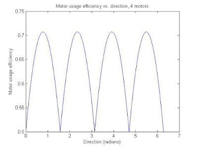
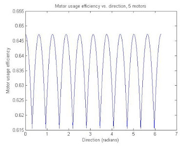
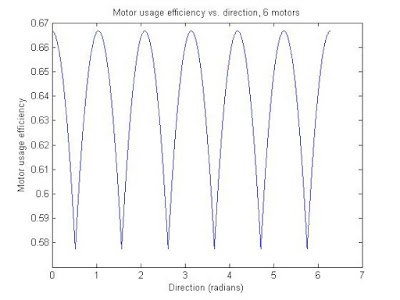
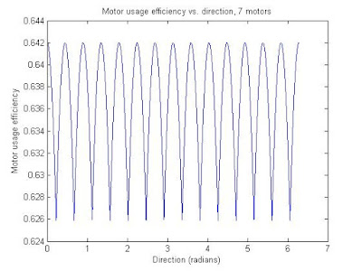
plot(theta,motorUse/motorCounts(j));
ylabel('Motor usage efficiency');
xlabel('Direction (radians)');
title(['Motor usage efficiency vs. direction, ' num2str(motorCounts(j)) ' motors']);
end

Thursday, January 5, 2012

Timing Pulley Transmission Calculator

Here is a nice calculator for setting up a new timing pulley transmission: http://www.sdp-si.com/cd/default.htm. It takes into account pulley center distance, belt sizes, pitch, speed ratio, and pulley tooth requirements. The nice thing is that the choices of materials is based on what is in stock at SDP/SI. I have ordered from them a few times.

Sunday, January 1, 2012

Changing Arduino Output PWM frequency

Here is a very useful post about changing the output PWM frequency on the Arduino (post #5). It was useful for me because I wanted a frequency over 20 kHz for DC motor control (>20 kHz is above the hearing range).

Getting PWM frequency and duty cycle with Arduino

Here is a simple code that reads a PWM signal and calculates its frequency and duty cycle in real time. The lack of an oscilloscope motivated this code.

The star of the show is the built-in 'pulseIn()' function, which gives the length of a low or high pulse. With these two measurements the calculation of duty cycle and frequency of the PWM signal is straightforward.

I have two different versions, simple and slightly longer.

The slightly longer code takes a user-specified time delay over which the maximum length is taken to help prevent truncation of a signal. For example, if an input pulse of 10 ms has already been running for 2 ms and the pulseIn function is called, it may return 8 ms. I am actually not sure if this is the way pulseIn works, but I tried both. With the default Arduino PWM frequency of approximately 490 Hz (http://arduino.cc/en/Reference/analogWrite), the slightly longer code returns 490 +/- 3 Hz, while the simple code returns 500 +/- 3 Hz. I tested this over low and high duty cycles. So it appears the slightly longer code has slightly better accuracy.

Simple code:
//Reads a PWM signal's duty cycle and frequency.
#define READ_PIN 13

#define PWM_OUTPUT 10

static double duty;
static double freq;
static long highTime = 0;
static long lowTime = 0;
static long tempPulse;

void setup(){
pinMode(READ_PIN,INPUT);
Serial.begin(9600);
analogWrite(PWM_OUTPUT,230);
}

void loop(){
readPWM(READ_PIN);
Serial.println(freq);
Serial.println(duty);
}

//Takes in reading pins and outputs pwm frequency and duty cycle.
void readPWM(int readPin){
highTime = 0;
lowTime = 0;

tempPulse = pulseIn(readPin,HIGH);
if(tempPulse>highTime){
highTime = tempPulse;
}

tempPulse = pulseIn(readPin,LOW);
if(tempPulse>lowTime){
lowTime = tempPulse;
}

freq = ((double) 1000000)/(double (lowTime+highTime));
duty = (100*(highTime/(double (lowTime+highTime))));
}


Slightly longer code:
//Reads a PWM signal's duty cycle and frequency.
#define READ_PIN 13
#define READ_DELAY 100

#define PWM_OUTPUT 10

static double duty;
static double freq;
static long highTime = 0;
static long lowTime = 0;
static long tempPulse;
static long lastSeen;

void setup(){
pinMode(READ_PIN,INPUT);
Serial.begin(9600);
analogWrite(PWM_OUTPUT,230);
}

void loop(){
readPWM(READ_PIN);
Serial.println(freq);
Serial.println(duty);
}

//Takes in reading pins and outputs pwm frequency and duty cycle.
void readPWM(int readPin){
highTime = 0;
lowTime = 0;
lastSeen = millis();
while((millis()-lastSeen)<read_delay){< div="">
tempPulse = pulseIn(readPin,HIGH);
if(tempPulse>highTime){
highTime = tempPulse;
}
}
lastSeen = millis();
while((millis()-lastSeen)<read_delay){< div="">
tempPulse = pulseIn(readPin,LOW);
if(tempPulse>lowTime){
lowTime = tempPulse;
}
}
freq = ((double) 1000000)/(double (lowTime+highTime));
duty = (100*(highTime/(double (lowTime+highTime))));
}