Showing posts with label Mechanical. Show all posts

Saturday, May 10, 2014

Specifications of the Turnigy TR-111

I recently bought two 11.5 HP gas engines from Hobby King. They are made by Turnigy and have the designation TR-111.

Turnigy TR-111 111cc Twin Cylinder Gas Engine 11.5HP

Surprisingly, there is no way to get any information other than on the product page. There is not even a mention of it on the Turnigy website. So, here I post information that I have gleaned from inspecting the engine myself. I planned to use these engines together to the power the same drive shaft to get about 23 HP. I picked the TR-111 engine because they were relatively cheap, lightweight (NW of 2.5 kg each), and satisfied my power target of over 20 HP.

To see it in action, check out the video from 'redsjcman' (who also has a review on the HobbyKing product page):


I do not have a video of my own yet, but hopefully I will soon.

Now, let us move on to the specifications.

First, the general specifications listed on the box:


MODEL: TR-111
DISPLACEMENT: 111.27 cc
BORE AND STROKE: 45 mm * 35 mm * 2
IGNITION: Electronic Auto Advance Ignition
SPARK PLUGS: CM-6
POWER RATING: 11.5 HP
PROPELLER: 26*12 27*10
SPEED RANGE: 1400 PPM - 7000 RPM
OIL: 25-40: 1 MIX (the octane number should be 93 or higher : lubrication Type of 2-cycle oil)
NW: 2.5 kg

I made measurements using this dial caliper from Harbor Freight. I use three significant digits.

Abbreviations:
ID = Inside Diameter
OD = Outside Diameter

CONTENTS:

4 x (Standoff Spacer, Bolt and Washer)


Standoff Spacer Dimensions:
-0.789" (20.0 mm) height (distance parallel to axis of symmetry)
-0.615" (15.6 mm) small OD
-0.782" (19.9 mm) large OD
-0.236" (5.99 mm) bore
Bolt Dimensions:
-0.188" (4.78 mm) unthreaded diameter
-0.328" (8.33 mm) head diameter
-0.161" (4.09 mm) minimum hex socket diameter (for 4 mm Allen / Hex key)
Washer Dimensions:
-0.205" (5.21 mm) ID
-0.471" (12.0 mm) OD
-0.041" (1.04 mm) thickness

2 x (Muffler, Gasket, and Pair of Bolts):


Muffler Dimensions:
-1.956" (49.7 mm) can diameter
-4.046" (103 mm) can length
-0.984" (25.0 mm) chimney diameter
-0.045" (1.143 mm) chimney thickness
-~3.75" (95.3 mm) chimney length
-0.384" (9.75 mm) hex key passage hole diameter
-0.591" (15.0 mm) mount rectangle height
-1.03" (26.2 mm) mount rectangle width
-0.222" (5.64 mm) mount bolt hole diameter
Bolt Dimensions:
-0.192" (4.88 mm) threaded diameter
-0.330" (8.38 mm) head diameter
-0.160" (4.06 mm) minimum hex socket diameter
Gasket Dimensions:
-0.864" (21.9 mm) overall height
-2.04" (51.8 mm) overall width

Engine:


Overall Dimensions (stripped down;unequipped with mounting hardware, ignition system, etc.):
(Please note these dimensions were not taken with a caliper, but with a ruler)
-6 11/64" length (excluding small shaft)
-10 5/32" width
-6 3/4" height

Engine Mounting Plate Dimensions:
-2.519" minimum distance between holes on shorter side.
-3.049" maximum distance between holes on shorter side.
By taking the average of the last two measurements, we can infer the hole center distance.
-2.784" (70.7 mm) center distance between holes on shorter side.
-3.435" maximum distance between holes on longer side.
-2.905" minimum distance between holes on longer side.
By taking the average of the last two measurements, we can infer the hole center distance.
-3.17" (80.5 mm) center distance between holes on the longer side.

Engine Small Shaft Dimensions:
-0.391" (9.93 mm) diameter
-1.571" (39.9 mm) length
-0.173" (4.39 mm) threaded hole inner diameter

Propeller Mounting Hardware:
6 x (Bolt, Washer, Split Lock Washer)
Cap


Bolt Dimensions:
-0.191" (4.85 mm) unthreaded diameter
-0.325" (8.26 mm) head diameter
-0.162" (4.11 mm) hex socket minimum diameter
Split Lock Washer Dimensions:
-0.217" (5.51 mm) ID
-0.324" (8.23 mm) OD
-0.053" (1.35 mm) thickness
Washer Dimensions:
-0.206" (5.23 mm) ID
-0.393" (9.98 mm) OD
-0.019" (0.483 mm) thickness
Cap Dimensions:
-1.676" (42.6 mm) OD
-0.398" (10.1 mm) bore
-0.153" (3.89 mm) thickness
-0.206" (5.23 mm) bolt hole diameter
-0.919" inner bolt circle diameter
-1.328" outer bolt circle diameter
From the average of the previous two, the bolt circle diameter can be inferred.
-1.1235" (28.5 mm) bolt circle diameter

From installed mounting spacer to shaft tip, the total length of the engine would be about 8.53".

Ignition System:


Text on the metal box:
CDI Rcexl
Automatic advancing angle ignition
for gas engines      Model:A-02
ELECTRONIC IGNITION
Voltage-Range: DC 4.8V/8.4V
Temperature Range: -40 degrees C / +60 degrees C

If you have any suggestions or requests, make a comment below.

Monday, February 24, 2014

Cutting Aluminum Sheet Metal: Plasma Cutters and Jig Saws

I have been working with a lot of thin aluminum sheet metal of 0.025" thickness, using a jigsaw with great efficacy. The cutting speed is not too slow, and the cut edges are very clean. There are no heat-affected zones; the jig saw does not produce excess heat that would effect the material properties in the proximity of the cut. There are some minor inconveniences however. The main one is limited maneuverability. As you may realize, a jig saw cannot do sharp corners or turns, but rather one long continuous cut. Also, sometimes when cutting from a large sheet it is inconvenient and slow to maneuver around, since for every cut you have to clamp down the work piece and shift the work piece around so that you do not cut into the table or whatever it is the work piece is resting on.

One of the most important advantages to the jig saw is that the tool and consumables (blades) are very cheap! The one I bought, pictured below, was only $30, with the set of 3 blades being only around $5.


I have also considered a plasma cutter. This much more high-tech option ionizes compressed air via an electric arc and turns it into plasma. The high-speed plasma jet is then used as the cutter by melting through the metal work piece very fast. Pictured below is one $650 model from Harbor Freight, which seems to be the most economical option for the average DIY-er. The advantages the plasma cutter has to offer is fast cutting and maximum maneuverability.

Chicago Electric Welding 60767 240 Volt Inverter Plasma Cutter with Digital Display

There remains questions for my aluminum sheet application whether the plasma cutter will produce a heat-affected zone and if the cut will be clean. I will have to try it out and report back later.

All in all, the jig saw is the best option for cutting aluminum sheet metal by far, because it is fast, cleanly cuts, and is extremely economical. I only considered the plasma cutter because I have a lot to cut, and I need it for other purposes and materials.

Saturday, February 22, 2014

Drilling Large Holes in Sheet Metal: The Step Drill Bit

Have you ever tried to drill large holes in sheet metal, for example, 0.5 inches in diameter? If you did with a regular drill bit (AKA twist bit), you may have had to quit due to the intense vibration and/or the hole turning out more like a Reuleaux triangle (below) rather than a perfect circle. The difficulty is special to thin sheets; the same drill bit will work on the same material of greater thickness.

File:ReuleauxTriangle.svg

I had many troubles with this, on both 7075-T6 aluminum (aircraft grade, 0.025") and stainless steel sheets (~24 gauge). Drilling large holes with twist bits seemed practically impossible. I tried different RPMs on my drill press as well as pilot holes, but nothing seemed to work well. I began to think that my 1/3 hp drill press was too weak. Before considering buying a new drill press, I decided to try the step drill bit from Amazon for around $12 (pictured below). The bits go to diameters of 1/2" and 3/4".


These things worked like a charm. Vibration and noise were reduced to the level of drilling small holes. Progressively larger diameters are drilled out step by step. These are the clear solution to drilling large holes in sheet metal. They also can be used to deburr rough holes and can function as all-in-one drill bits for materials as thick as the steps.

Wednesday, February 12, 2014

Mechanical Fasteners: (Blind) Rivets

I have recently become aware of a strong, efficient, and economical way to fasten metals together: the blind rivet. I have always heard about how rivets were used in aircraft production, and for some reason I never seriously considered using them in my own mechanical projects. I wrongly assumed the cost and complexity was too high for someone with a hobbyist's budget. It turns out blind rivets are very practical and economical even for me.

As I am working with aircraft-grade aluminum (7075 T6), I cannot weld pieces together. Aluminum is notorious for being difficult to weld well, and this applies even more so for the stronger aircraft-grade aluminum alloys. Welding these alloys are usually deemed ineffective, especially when the resulting material strength is important. With welding out the window, I racked my brain for alternatives to heavy screw and nut arrangements, and came across the blind rivet.

As you noticed, there is a specific type of rivet I am referring to: the 'blind' rivet. A regular rivet is a solid pin-looking thing where you have to hammer down and flatten one end. A blind rivet is a rather complicated-looking thing if you have never seen one before, but it can quickly and easily be implemented with a tool that you can buy for less than $20 at your local hardware store. Also, with blind rivets you do not require access to both sides of the joint, only one side is required, hence the name 'blind' rivet. You can Google up many great explanations and visual demonstrations of how blind rivets work.

Blind rivets are economical. On McMasterCarr, I can buy 1/8" diameter aluminum blind rivets at 250 for less than $10. It was actually more economical than the alternative for me, which were socket cap screws of similar size.

I would argue that the space and weight efficiency, for a given bore size, of the rivet is greater than that of screws. Strength of screws are diminished because of the required space for the threads. The screw nuts can be heavy when many screws are needed.

The downside of a rivet compared to a screw is more complicated dis-assembly. You have to destroy the rivet if you want to unfasten something, but it is not too difficult to remove a rivet.

Blind rivets today are the product of many years of improvements from field use. They are extremely effective if welding is not an option and you need a strong, lightweight bond between metal plates.

Monday, January 9, 2012

More omniwheel-drive control considerations

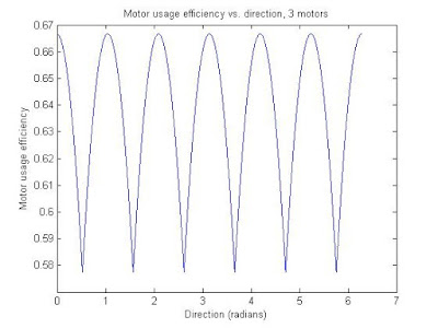
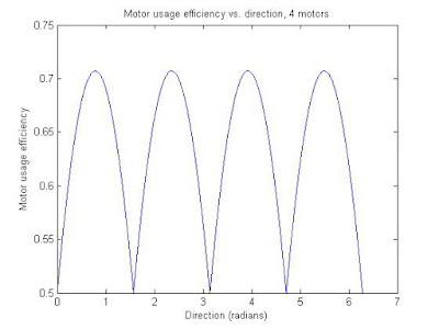
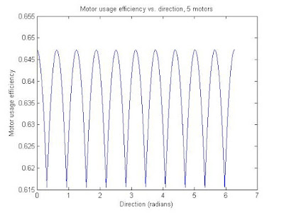
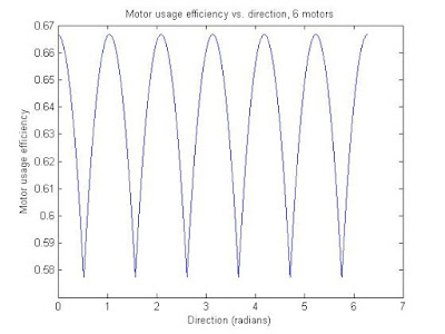
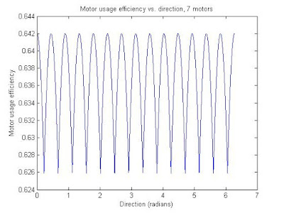
Here are some plots and MATLAB code that shows the relationship between the net contribution of the motors versus direction, for different numbers of motors/wheels on the vehicle. The 'net contribution' of the motors was calculated by adding the absolute value of the motor wheel direction (contribution direction) dotted with the direction of the vehicle's movement. The motor usage 'efficiency' is the same figure as described, but divided by the number of motors. An efficiency of 1 would be where all the motors are lined up and going the same direction, which will not happen with an omniwheel vehicle. The efficiency consistently floats around the .6-.7 range, which is pretty good. Meaning if I use 5 of these 135-watt DC motors, I would get about 440 W of rated DC power driving around. Not bad.

The code also includes last post's stuff (the speed consistency vs. direction plots). Again, even/odd wheel numbers are in their own trend groups, and as the number of motors go up the standard deviation of the efficiency with respect to direction goes down.

The efficiency plots:
The code:
%FPS bot testing
close all;
offsetAngles = [0 0 0 0 0];%Just the difference in angle between frontmost motor and forward direction.
motorCounts = [3 4 5 6 7];
motorAngles = 2*pi./motorCounts;
for j = 1:numel(motorCounts)
mvec = zeros(motorCounts(j),2);
for k = 1:motorCounts(j)
mvec(k,:) = [cos(offsetAngles(j)+(k-1)*motorAngles(j)) -sin(offsetAngles(j)+(k-1)*motorAngles(j))];
end
resolution = 10000;
theta = linspace(0,2*pi,resolution)';
directionVector = zeros(resolution,2);
directionVector(:,1) = cos(theta);
directionVector(:,2) = sin(theta);
%Speed
mag = zeros(resolution,1);
currentMag = zeros(motorCounts(j),1);
for k=1:resolution
for i=1:motorCounts(j)
currentMag(i) = abs(mvec(i,:)*directionVector(k,:)');
end
mag(k) = max(currentMag);
end
figure;
plot(theta,mag);
ylabel('Normalized speed magnitude');
xlabel('Direction (radians)');
title(['Normalized speed magnitude vs. direction, ' num2str(motorCounts(j)) ' motors']);
%Torque
motorUse = zeros(resolution,1);
for k=1:resolution
for m=1:motorCounts(j)
motorUse(k) = motorUse(k)+abs(mvec(m,:)*directionVector(k,:)');
end
end
figure;
plot(theta,motorUse);
ylabel('Equivalent motor usage (# of motors)');
xlabel('Direction (radians)');
title(['Motor usage vs. direction, ' num2str(motorCounts(j)) ' motors']);
figure;
plot(theta,motorUse/motorCounts(j));
ylabel('Motor usage efficiency');
xlabel('Direction (radians)');
title(['Motor usage efficiency vs. direction, ' num2str(motorCounts(j)) ' motors']);
end

Thursday, January 5, 2012

Timing Pulley Transmission Calculator

Here is a nice calculator for setting up a new timing pulley transmission: http://www.sdp-si.com/cd/default.htm. It takes into account pulley center distance, belt sizes, pitch, speed ratio, and pulley tooth requirements. The nice thing is that the choices of materials is based on what is in stock at SDP/SI. I have ordered from them a few times.

Monday, December 26, 2011

Updates

I have my biggest project yet coming up soon. I have not been posting about it, even though I have been working on it for several weeks, and thinking about it and planning for months. What is holding me back is that I am on break, and school is closed. I need to use my school's water-jet cutter, and I will do that ASAP when school starts and the machinery becomes available.

Sunday, December 11, 2011

Omniwheel vehicle speed consistency

I am currently working on an omniwheel drive vehicle with a rather... unique control system. I am estimating it will be done by January. It involves wireless Arduino serial communication via XBEE, water-jet cut custom aluminum parts, h-bridge PWM DC motor controllers, and mutilated IKEA furniture, haha.
This post is about some speed control considerations on a vector-based control algorithm. Depending on what direction you going in, the speed will differ, because the wheel orientations change. Obviously, for a good human-operated vehicle this speed difference must not be too great. If the direction is aligned with the wheel's normal rolling direction, the speed will be at a maximum. The wheel most aligned with the direction of movement will dictate the top speed of the vehicle. All other wheels will provide moment balance and extra torque.
Below are some plots showing the normalized (meaning min is 0, max is 1) speed vs. direction, in radians. The different plots are for different numbers of motors/wheels installed on the vehicle.

As you can see, for 3 and 4 motors the speed difference is quite significant. For three motors, the lowest speed depending on the direction of vehicle movement can be about 14% lower than the normal speed (in the graphs it would be 1). Four motors fares even worse, which can be surprising at first glance. Four motors give a minimum speed around 30% lower than the normal speed.
A few interesting patterns can be seen here. The number of dips equals the number of wheels/motors if the number of wheels/motors is odd, and twice the number of wheels/motors if the number is even. Also, locally the speed difference is minimized if the number of wheels/motors is odd. 5 wheels/motors is a reasonable number that gives an acceptable speed difference, <5%. Of course, all of this can be fixed to give virtually no speed difference consistent speed in the controller's software.
This was a very interesting investigation! The code to generate the plots above was written in MATLAB and is included below (MATLAB is not free, but SCILAB is! And it is very similar! It will probably run the code with little or no modification!):

%FPS bot testing
offsetAngles = [0 0 0 0 0];%Just the difference in angle between frontmost motor and forward direction.
motorCounts = [3 4 5 6 7];
motorAngles = 2*pi./motorCounts;
for j = 1:numel(motorCounts)
mvec = zeros(motorCounts(j),2);
for k = 1:motorCounts(j)
mvec(k,:) = [cos(offsetAngles(j)+(k-1)*motorAngles(j)) -sin(offsetAngles(j)+(k-1)*motorAngles(j))];
end
resolution = 10000;
mag = zeros(resolution,1);
theta = linspace(0,2*pi,resolution)';
directionVector = zeros(resolution,2);
directionVector(:,1) = cos(theta);
directionVector(:,2) = sin(theta);
currentMag = zeros(motorCounts(j),1);
for k=1:resolution
for i=1:motorCounts(j)
currentMag(i) = abs(mvec(i,:)*directionVector(k,:)');
end
mag(k) = max(currentMag);
end
figure;
plot(theta,mag);
ylabel('Normalized speed magnitude');
xlabel('Direction (radians)');
title(['Normalized speed magnitude vs. direction, ' num2str(motorCounts(j)) ' motors']);
end

Thursday, November 10, 2011

Long time, no post: CFD and Carbon Fiber Prototyping

It's not that I have been on a project hiatus, I have been hard at work with CFD simulations, researching a possible invention! So I do not want to post everything I have done just yet. But I will be posting the physical prototype I have referred to in a past post, made of water-jet-cut aluminum plate, driven by a ~600W brushless motor. It was made to validate CFD cases, and I gained some insight from it. I have also made a YouTube video of my first FanWing CFD case public. It was done a long while ago.


I have been working on clustering computers, that is connecting by ethernet cable more than one desktop together and using their processors to work on one case together. I am doing it on Ubuntu 10.04LTS and using OpenFOAM 1.5-dev. I will have results shortly. Useful link: Clustering computers

I am now investigating building carbon fiber models, and I will see if I can do myself rather than have a prototyping service do it.

Wednesday, February 16, 2011

Putting together a prototype/validation for CFD...

This is my second foray into building something mechanical, my previous venture utilizing only junkyard parts to build a testing platform for something similar to the Fanwing last summer (this is before I even touched CFD, and is incidentally why I picked up CFD). It ended up weighing 80 pounds, using a 5hp motor I had used in 8th grade to power a massive, hot roller mill for making rubber bands for a science fair project (10+ ingredient chemical recipes, fun times) and v-belt transmission for a cross-flow-fan test section of about a foot in diameter and less than 2 feet in span (picture of it here maybe if i remember). I guess it ended up not being very useful, but for the amount of metal-working and welding I had to do, I have at least a modicum of pride in it.

Anyways this time I used all of the internets to find non-junkyard parts for use in conjunction with a water jet cutter, which is awesome and I now have access to, to build a prototype for CFD validation. The design in Autodesk Inventor (which, unlike SolidEdge ST3, allows easy use and integration of variables for dimensions so you do not have to redo your whole design if you need changes in a few parts) looks very tight and I am excited to build it.

Anyways, I always post to share something that I think may be useful. For this post, it is some vendors in case you are planning to build something:
Main vendors:
- McMaster-Carr (Everything mechanical)
- Hobby King (Motors, batteries, etc.)
Places that had stuff that the main vendors did not have:
- SDP SI (Has a whole lot of mechanical stuff, but I used them for their extensive variety of timing belt pulleys)
- Fastenal (For 4-40 square nuts, and if you do not want to buy set screws or square nuts, etc. by the 100's or more)
- Digikey (Angle brackets; usually an electronics supplier; I bought PIC microcontrollers from these guys before; Use google to search their stuff)

Although this post feels pretty unsubstantial, it is but the calm before the storm of substance, if you will. I will be posting more about my mechatronic CFD validation, uhh... machine.